

Hydraulic Solenoid Valve | Van Điện Từ Thủy Lực Là Gì

Hydraulic Solenoid Valve - How They Work
- A hydraulic solenoid valve is a solenoid controlled directional valve used in a hydraulic system for opening, closing or changing the direction of flow of the liquid. The valve operates with a solenoid, which is an electric coil wound around a ferromagnetic core at its center. The valve consists of various chambers also called ports. The solenoid is used for sliding the spool within the valve, opening or closing the ports. The spool is the cylindrical component which serves the function of the valve by either blocking or allowing the flow of liquid through these ports, depending upon its position.
- Hydraulic solenoid valves are widely used in industries like manufacturing, aerospace, construction and many others that require hydraulic systems. Figure 1 is an example of a hydraulic solenoid valve.
______________________________________________
Directional Hydraulic Solenoid Control Valves
- The directional control valves are designed to start, stop or change the direction of the fluid flow. These valves are most commonly used in hydraulic and pneumatic systems. We discuss only the hydraulic applications for the purpose of this article.
- Hydraulic solenoid valves: The hydraulic solenoid valve is a directional control valve widely used in hydraulic systems to change, allow or restrict the flow of liquid. The valve uses solenoids (X and Y) on either side of the valve for actuation as seen in the figure below. The valve consists of a cylindrical spool (Z) with land (larger diameter) and grooves (smaller diameter). The land blocks the flow while the groove allows the flow through the valve.
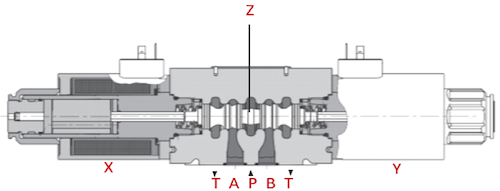
Figure 2: Components of a 4/3-way hydraulic solenoid valve: spool (Z), solenoid on either side (X and Y), and ports (T, A, P, B)
______________________________________________
- The directional valves are generally represented by the number of ports and number of switching positions. In the 4/3-way valve hydraulic valve in above, 4 represents the number of ports and 3 represents the number of positions. P is the pressure port, A and B are working ports and T is the return port.
- When the solenoid X is actuated, the spool is pulled towards the left by the electromagnetic force. When solenoid Y is actuated, the spool slides towards the right. This sliding of the spool opens, closes or changes port connections, which alters the direction of the flow.
______________________________________________
Hydraulic Solenoid Valve Design
• 4/3-Way Hydraulic Solenoid Valve
- A 4/3-way valve has 4 ports and 3 positions. It is the most common type of valve used in hydraulic circuits. Depending on the spool design, ports can be open, closed, or connected to certain inputs/outputs. Figure 3 below is a common example, but there are additional spool designs. The spool below can be in 3 different positions: P-A and B-T (Figure 3 left), closed (Figure 3 middle), or A-T and P-B (Figure 3 right).
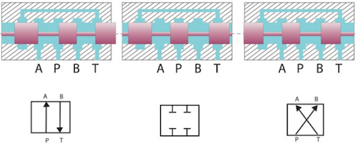
Figure 3: Working principle of 4/3-way solenoid valve
______________________________________________
- As seen in circuit function 1 (Figure 3 left), when the spool is moved to the right, port A is connected to port P and port B is connected to port T. Circuit function 2 (Figure 3 middle) represents a closed center valve with all the ports blocked. When the spool is moved to the left, port P is connected to port B and port T is connected to port A.
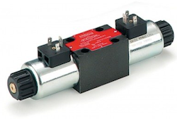
Figure 4: 4/3-way valve
______________________________________________
• 4/2-Way Hydraulic Solenoid Valve
- A 4/2-way valve has 4 ports and 2 positions. A and B are two working ports, P is the pressure port and T is the return port.
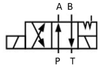
Figure 5: Circuit function of 4/2 way valve
______________________________________________
- These valves can have a single or double solenoid design. They can be connected in a normally open or closed position, therefore, there is a spring to return it to its normal position. A single solenoid valve shifts the spool when the solenoid is actuated and returns to the original position once de-energized. In a double solenoid valve, the spool shifts when one solenoid is energized and returns when the other is energized. It is important to note that only one solenoid should be energized at any given time.
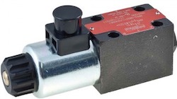
Figure 6: 4/2-way valve with one solenoid
______________________________________________
• Hydraulic Solenoid Valve Design Options
- These hydraulic solenoid valves are available with features like socket head cap screws with hexagon socket, magnetic coil, sealing set for Pohl tube, O-ring set for connection plates or, blind plate including 4 O-ring. These features support reliable fastening and tight sealing to prevent leakage during the process.
Detent Mechanism
- A detent mechanism can be a magnetic or mechanical catch to prevent the motion of the spool. Some hydraulic solenoid valves use this detent mechanism to hold the spool in an open or closed position when de-energized. When energized, the spool is released, and it returns to its original neutral position. In a 2-position valve, the valve can be detented for spool to remain in either position. For a 3-position valve, the valve can be detented to remain in any of its three positions.
Industry Examples
Hydraulic solenoid valves are used in a wide range of applications that use a hydraulic system. Common hydraulic solenoid valve applications are:
- Water supply system
- Turbine system
- Fuel/gasoline supply system
- Wastewater treatment plants
- Process control in manufacturing plants
- Hydraulic motors, breaks, pumps in automotive industry
- Hydraulic machinery in aerospace and marine industries
- Heavy machinery in construction and landscaping
- Machinery in agricultural sectors
Points of Attention & Selection Criteria
- Number of ports and positions: This should be selected based on the requirement of your application.
- Spool action: This should be based on whether your application requires the spool to return back to the center or stay in place when deenergized.
- Flow: The flow requirement for the application will help in determining the size of the valve.
- Material: The material of the valve should be compatible with the properties of flowing media.
- Temperature: The valve materials can withstand the minimum and maximum temperature requirement of your application. Temperature is also essential in determining valve capacity as it affects the viscosity and flow of the fluid.
- Pressure: The valve must be able to withstand the maximum pressure required for your application.
Mua Van Điện Từ VINDEC
- Thời gian bải hành 12 tháng theo tiêu chuẩn lắp đặt và sử dụng của nhà sản xuất.
- Miễn phí vận chuyển trong vòng 20 km nội thành Hà Nội
- VINDEC cam kết cung cấp đúng chủng loại sản phẩm do chính hăng sản xuất mà chúng tôi đang cung cấp, đảm bảo chất lượng, đúng nguồn gốc, đầy đủ chứng từ nhập khẩu.
- Quý khách hàng có thể tìm kiếm hoặc Download Catalogue sản phẩm của hãng tại Website của chúng tôi với thông số kỹ thuật rõ ràng chính xác nhất của hãng: VAN ĐIỆN TỪ
- Thêm vào đó, VINDEC chúng tôi có Kho Hàng tại Hồ Chí Minh và có Kho Hàng + Xưởng Sản Xuất với diện tích trên 2.000m2 tại Hà Nội.
- VINDEC với năng lực và kinh nghiệm gần 20 năm cùng với đội ngũ kỹ sư giầu chuyên môn, chúng tôi tự đáp ứng được các dự án lớn về hàng VAN CÔNG NGHIỆP chúng tôi luôn đồng hành cùng phát triển.
Admin: VINDEC


